SGI O2
In September 2009 I started to downsize this collection to a few items and then archived this section to its own subdomain at the start of October 2011.
This system
In January 2006 I spotted an offer on one of the mail lists at work for a
number of unwanted SGI systems, to be exact four different Indy's
and an O2. Luckily I responded quick enough for my request for the R5000 Indy and
the O2 were accepted.
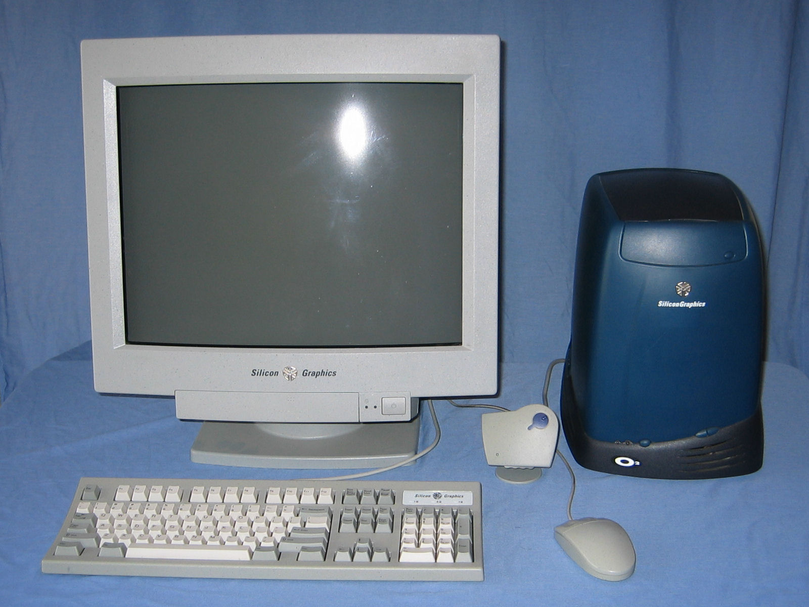
The O2 system is the lowest CPU model (180Mhz R5000 with no L2 cache) but it
does have the full I/O module and 256MB of RAM. The peripherals I got with is
include a SGI branded 20" display, keyboard and mouse, and the (apparently
rare) O2 camera.
In April 2007 I acquired a SGI 1600SW display with a MultiLink Adapter
which became part of this system, replacing the 19" CRT.
Images
 |
o2-01.jpg, 1600x1200, 240KB |
| Complete system after I got the 1600SW display with keyboard, mouse and
the O2 camera.
|
 |
o2-01a.jpg, 1600x1200, 236KB |
| Complete system as I originally got it with the O2, 19" display,
keyboard, mouse and the O2 camera.
|
 |
o2-02.jpg, 1600x1200, 277KB |
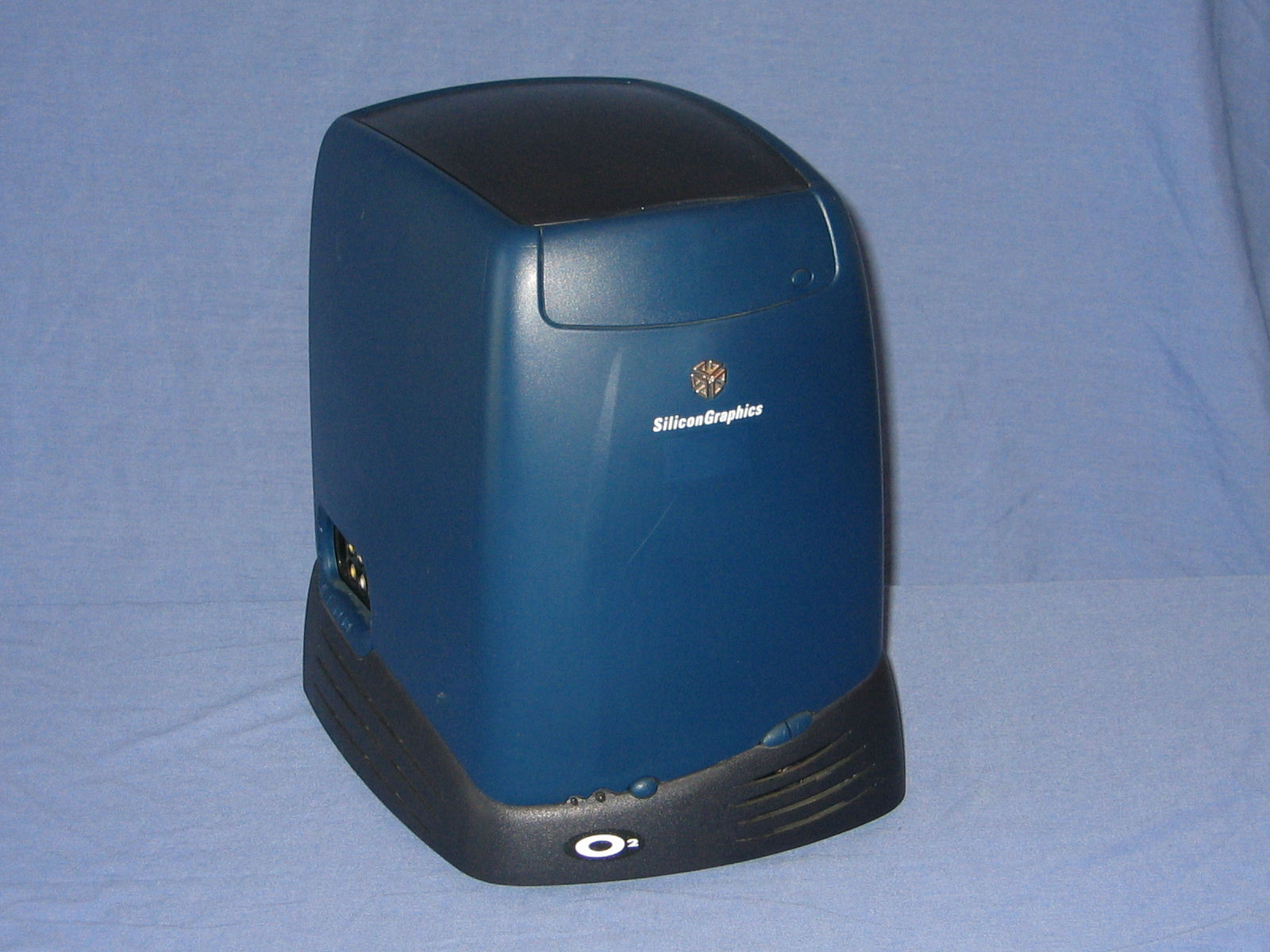
| The front of the unit features a CD-ROM drive at the top above the SGI logo.
Across the bottom are a reset button, power indicator, power switch and volume
controls.
|
 |
o2-03.jpg, 1600x1200, 230KB |
| The CD-ROM is standard drive with a custom faceplate attached to the tray that
is matched to the overall skin of the unit.
|
 |
o2-04.jpg, 1600x1200, 276KB |
| The rear of the unit contains the standard assortment of ports (video, mouse,
keyboard, parallel, scsi, etc) while on the left side (when viewed from the
front) features an array of audio and video inputs and outputs. This is a
R5000 CPU model which means it has two hard drive bays (only one is populated).
|
 |
o2-05.jpg, 1600x1200, 304KB |
| The mainboard, hard drives and I/O module simply slide out of the chassis once
their retaining lever is released. The flat black piece of metal slots into
the rear of the unit and when a lock (laptop type) is attached the removal of
these modules is prevented.
|
 |
o2-06.jpg, 1600x1200, 284KB |
| A view from the rear of the empty chassis once the modules and power supply
have been removed. Apart from the backplane that connects the modules together
the only component that remains is the CD-ROM drive in the upper section.
|
 |
o2-07.jpg, 1600x1200, 265KB |
| The black top piece of the skin can be removed by releasing a catch near the
power supply. At this point it is possible to remove the blue section of the
skin which would allow the CD-ROM drive to be removed.
|
 |
o2-08.jpg, 1200x900, 179KB |
| The motherboard module. On the left side are the eight proprietary RAM slots
(six are populated with a total of 256MB) and on the right side is the bracket
for a PCI card.
|
 |
o2-09.jpg, 1600x1200, 419KB |
| Removing the PCI bracket exposes more of the logic board including the CPU
module which contains a 180Mhz R5000 CPU.
|
 |
o2-10.jpg, 1600x1200, 344KB |
| A closeup of the ports on the motherboard module. From left these are SCSI,
parallel, VGA (standard DE-15, not 13W3), ethernet, two serial, keyboard and
mouse. Above the video and parallel ports is the space where the adapter for
the SGI 1600SW display is installed
and above all of the ports is the back of the PCI slot.
|
 |
o2-11.jpg, 1200x900, 211KB |
| A closeup of the locking lever for the motherboard module. A pin inside the
chassis runs along the slot on the back of the module until it fits into the
lever. When the level is closed it pulls the module into the case as the pin
moves along the curved slot. The hard drive and I/O modules have a similar
mechanism.
|
 |
o2-12.jpg, 1200x900, 194KB |
| This I/O module provides both input and output for S-Video, composite video and
sterero audio. The last two ports on the side are for headphones and a
microphone and the rear of the module contains an audio line-out and the port
for the O2 camera.
|
 |
o2-13.jpg, 1200x900, 184KB |
| A hard drive module. This is essentially a plastic frame for a standard SCSI
hard drive with a SCA connector.
|
 |
o2-15.jpg, 1600x1200, 205KB |
| The front of the 1600SW display showing the few scuff marks on it.
|
 |
o2-16.jpg, 1600x1200, 257KB |
| The rear of the 1600SW display showing the off-centre stand. Next to
the video cable are sockets for power (left) and the colour lock sensor
(slightly below).
|
 |
o2-17.jpg, 1200x900, 141KB |
| The top of the MultiLink Adapter features controls for adjusting the
display and a power LED.
|
 |
o2-18.jpg, 1200x900, 157KB |
| The rear of the Multilink Adapter features an analog/digital switch,
DVD-I input, a blank space, the LVDS output, and a power connector.
|
 |
o2-19.jpg, 1600x1200, 238KB |
| The SGI O2 Flat Panel Accessory Kit includes: Flat panel monitor adapter
board, reversible phillips/flat screwdriver, antistatic wrist strap,
installation guide, software updates CD-ROMs, software installation
guide, and the ColorLock sensor.
|
 |
o2-20.jpg, 1200x900, 287KB |
| The SGI O2 flat panel monitor adapter board.
|
 |
o2-21.jpg, 1200x900, 163KB |
| The ColorLock sensor that is used to calibrate the flat panel display.
|
 |
o2-22.jpg, 1200x900, 134KB |
| Installation discs for SGI IRIX 6.5.14.
|
Other resources